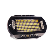
We appreciate your purchase of AutoLEDTech.com's 2015-2018 Dodge Charger RGBW +A DRL boards! Please follow the steps detailed below to properly install your replacement DRL boards.
Please note: Headlights must be opened before proceeding with installation. Professional installation is strongly recommended.
Tools Needed: Torx T15 and T20 Screwdriver
1. First, access the factory LED panels by removing the 4 screws holding the black bezel in place using a T20 bit. Once removed, pull the bezel off and set it to the side.
2. Next, remove the torx screws holding the black alignment bracket in place over the factory boards. Pull the bracket off and unclip the power connector from the factory board. Remove the final torx screw holding the factory board in place.
3. Using a firm grip, pull the factory board off and remove the thermal adhesion pad (sil-pad) from the back of the factory board. Reattach the sil-pad to the back of your new Diode Dynamics board.
4. Using the alignment tabs, place the new board into place and replace the original retaining screw. Next, replace the black alignment bracket using the original screws. DO NOT OVERTIGHTEN.
5. Repeat this process for other two LED boards in the headlamp.
6. Once complete, route the ribbon cables out of the headlamp through the dust cap, sealing any holes that you may create.
7. Using the alignment tabs, reinstall the black bezel. Once complete, replace the original torx screws and headlamp lense. Repeat for other headlamp.
8. Connect the LED Board connector to the specified RGBW Driver connector. Next, connect the RGBW Driver to the 4-way splitter that is connected to the RGBW Controller. The bare wires from the splitter must be inserted into the corresponding slot on the controller in order for the boards to function properly
(Red wire->R | Green wire->G | Blue wire->B | White wire->W | Black wire->+)
IMPORTANT: DO NOT plug the LED Board connector directly into controller without the driver. The LEDs must be plugged into driver first to control the power. Failure to do so will result in damage to the LED Board and WILL NOT be covered under warranty.
9. Connect your RGBW controller to 12V power and ground. This will dictate when the LED Boards turn on. The most popular wiring choices are listed in the table below. NOTE: The LED Driver Module will have one YELLOW and one BLACK wire that will need to be connected in order for the DRL boards to function properly. The black wire of each Driver Module must be connected to a ground wire/location separate from the main controller ground!
| Voltage | Pin OEM Connector | Wire Color-Driver | Wire Color-Passenger |
| 12V+ | Pin 3: DRL | White/Yellow | White/Dark Blue |
| 12V+ | Pin 4: Parking | White/Brown | White/Orange |
| BLACK | Pin 10: Ground | Black | Black |
| YELLOW | TURN SIGNAL | White/Light Green | White/Tan |
10. Mount the drivers and controller, and tuck all wires. Drivers should be mounted outside of headlight for serviceability, in a location away from the engine block to avoid excessive heat buildup. The controller needs to be mounted in a position that avoids moisture or excessive heat. Test thoroughly, reseal headlights, and reinstall onto vehicle.

