Standard RGBW +A LED Halo & DRL Wiring Guides

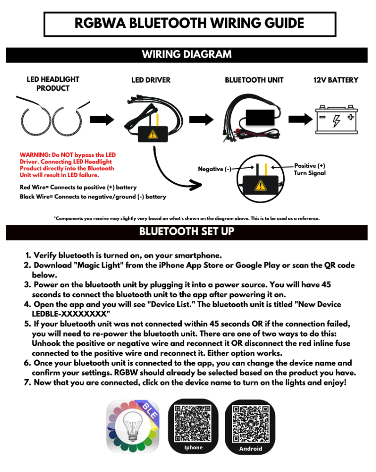

Powering the Wiring Harness (Flow Series or RGBW)
The flow series wiring harness will now need to be connected to 12V+ and Ground/-. The wire with the inline fuse is the + wire, the other one without the inline fuse holder is -. You can connect these directly to the vehicles battery, but the harness will always be receiving power. This means that you will have to manually turn the halos/DRLs on and off every time you exit the vehicle. We recommend clipping the hoop connector off of the 12V+ wire and using an "add-a-fuse" or fuse tap and tapping the 12V+ power into a fuse that turns on/off with the vehicle or with a switch inside of the vehicle. All vehicles are different, so you will need to research or test which fuses are ignition-powered to do this. If you are going this route, then the ground/- wire will likely need to be connected to the frame ground nut that is located near the fuse box. It is a nut attached to the metal of the vehicle that the fuse box ground/- wires run to.
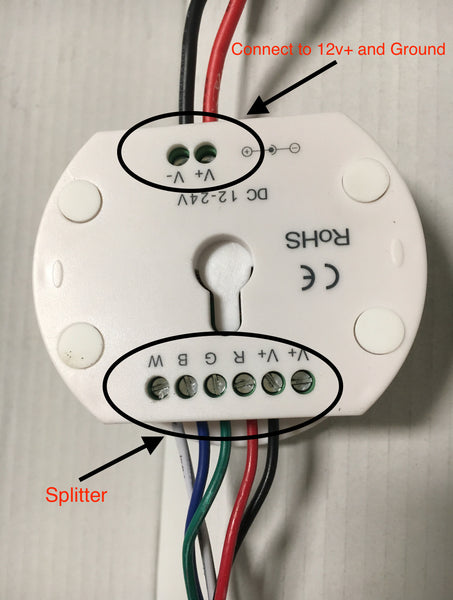
Old Style Controller:
Step 1: Insert the splitter wires into the appropriate controller outputs. Use a small flathead screwdriver to tighten down each connection.
Step 2: Run 12v+ and ground from your preferred power source into the input connections on the controller. Use a small flathead screwdriver to tighten down each connection.
Step 3: Connect the LED driver(s) input connection to one of the splitters output connection(s)

Step 4: Splice the yellow wire (Turn signal + input) to the positive wire of the (left or right) turn signal on the vehicle. Splice to black wire to the ground wire of the (left or right) turn signal on the vehicle, or ground it to the frame.
PLEASE NOTE: the ground connection for the turn signals must be different than the ground connection for the controller. The left and right turn signal grounds must also be separate. The ground connection of each turn signal input on the LED drivers MUST be connected in order for the LED boards to function.

Step 5: Connect the LED driver output connection to the LED replacement board input connection. Ensure that the LED driver connected to the (left or right) turn signal is connected to the (left or right) LED replacement board.

PLEASE NOTE: If the LED replacement boards are producing a "washed-out" or faded color output, the white LEDs are on! Turn the white LEDs off in the app by going to the "Warm" settings and clicking the black circle to disable them. The "Warm" settings control the white LEDs on the replacement boards.